Making a Capsule Mesh via Script in Five 3D Environments
Unity, Processing, Godot, Blender, Three.js

This tutorial explores how to generate a capsule through script in five 3D environments. Or rather, how to approximate a capsule with a mesh. We’ll look at two game engines, Godot and Unity; one modeling suite, Blender; one creative coding IDE, Processing; and one browser-based tool, Three.js. We leave it to others to judge which APIs are better or worse.
There should be no illusion that learning to make a capsule is in itself useful; however, understanding how to make one shape across APIs can lay the groundwork to create many more. Since we’ll use some basic interface scripting in Unity and Blender, concepts for extending editor functionality will crop up as well.
This tutorial is organized as follows:
For those who wish to see the end results, a Github repository is here. The software version used is specified at the start of each implementation.
Conceptual Planning
For our purposes, a capsule is akin to a UV sphere. Like a globe of the Earth, a capsule has longitudes, vertical lines demarcating a progression from West to East relative to a prime meridian. Furthermore, it has latitudes, horizontal lines demarcating a progression from South to North relative to two poles.

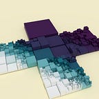
A capsule can be cut and unfolded so that it creates a two-dimensional net. In this thought exercise, the prime meridian is cut into two edges. A hole is poked in the North and South poles and the capsule’s polar caps are cut into triangles. However, unlike a globe, a capsule has two equators surrounding a central cylinder.
Regions & Faces
To create the illusion of a smooth surface, capsules typically need a minimum of 32 longitudes and 16 latitudes. We’ll reduce the count to 8 longitudes, 4 latitudes, and 1 ring between the capsule’s two equators to make the capsule’s faces easier to see and to count.
Next, we separate a capsule into the following regions: North cap, North hemisphere, cylinder, South hemisphere and South cap. Looking at the faces in these regions,
- The North and South caps are comprised of triangles, one for each longitude. In this example, 8 triangles at the start and end, summing to 16. Each triangle’s peak is perpendicular to the midpoint of the opposite edge.
- The North and South hemispheres consist of 4 latitudes, divided by 2, minus 1. The North and South cap account for the last latitude, hence the minus 1. This gives us either 8 quads for the North and another 8 for the South; double that figure if we split the quads into triangles.
- The cylinder has 32 tris or 16 quads as a consequence of being divided in half by 1 ring.
Suppose we were to rebuild this capsule, starting at the North pole and adding one face at a time. We could expand our list of created faces as we progress until we reach the South pole. In code, this would be facilitated by generic collections in Java and C# like List, the push method of JavaScript arrays, or the append method of Python and GDScript lists.
By tracking the number of vertices and faces in each region, we know how many elements we need to create before we start filling a list. We can assign data in each region out of order, allowing us to start at the North and South pole, assign data to both, then move inward to the central cylinder. Furthermore, we can consolidate the loops which calculate vertex data and loops which set face indices.
As the 2D net above suggests, our approach in code will be the same as it is would be with any other grid. Just as we would fill an image’s one-dimensional array of pixels using nested for-loops, so too here. (Conversely, we could use a one-dimensional loop and convert to two dimensional coordinates using i % w and i / w.) There will be complications insofar as we only need to work with half of our latitudes at a time, but the fundamentals remain the same.
Vertices
Next, let’s look at data associated with a vertex. How much data a vertex holds depends on the renderer, material shaders, and so on. We’ll only focus on three: a coordinate, texture coordinate and normal.
In the example above, the number of unique elements per vertex are unequal:
- There are 42 coordinates. The first and last coordinate (0 and 41) are repeated at the apex of each polar cap. Each latitude is periodic. In a 2D projection, it appears as though coordinates 1, 9, 17, 25 and 33 are referenced twice; in 3D, this is the prime meridian.
- There are 60 texture coordinates (UVs). At the polar caps, we have a UV for every longitude; this is the exception. Otherwise, UVs are not periodic; for each latitude, we have longitudes + 1 texture coordinates.
- There are 25 normals. In many cases, a smooth shaded mesh will have a 1:1 ratio of coordinates to normals. The capsule is an exception. Since the cylinder between the equators is flat, there’s no need to recalculate a new normal per each ring; normals 9–16 are repeated.
To create the normals and coordinates, we use conversions from spherical and cylindrical to Cartesian coordinates. The cylindrical conversion is:

As we’ve seen before, the spherical conversion is described with either f or g:

where theta (θ) symbolizes the azimuth, or longitude; phi (ϕ) symbolizes the inclination, or latitude; and rho (ρ) symbolizes the radius. We’ll be using the variant g because it accepts a signed range for the inclination from -π/2 to π/2. The progression from the North to the South pole is linear while the progression around the equator is periodic. For normals, the radius is assumed to be 1 and can be removed from the equation.

We can also take advantage of periodic shifts to avoid calculating the cosine and sine of an angle twice for the hemispheres.

If we do not wish to calculate normals in parallel with coordinates, we can use the formula above to derive a vertex’s normal from its coordinates. a, b and c are the triangle’s corners. The × symbolizes the vector cross product. A face normal is found by summing vertex cross products, then normalizing. This is why vertex winding matters.

A counter-clockwise face’s normal will be a negation of a clockwise face’s. Depending on the engine, a capsule with backwards winding may look inside-out or black. (Vertex winding should not be associated with the slant of the diagonal formed when a quadrilateral is split into two triangles.)
Furthermore, different graphics engines use different Cartesian coordinate systems. In Blender, (0.0, 0.0, 1.0) is up; in Unity, (0.0, 1.0, 0.0) is up. Blender is a right-handed system; Unity is a left-handed system.

We’ll operate on the assumption that z-up is the default, and will transpose and negate our results as needed for y-up systems. When in doubt, use a diagnostic mesh, such as the one above, to see the impact of these differing systems.
It should not be assumed that UVs are standardized either. The top-left corner is typical in OpenGL; in Blender, bottom-right is the origin.
Correlating these three types of vertex data is not always obvious. If we create three arrays of unequal length with the minimum number of elements for each, then we need a compound indexing system. A vertex must track three indices for each array. To illustrate, here is a print of the North polar cap for the example capsule:
We may have to revisit elements face-by-face and create duplicates anyway, as is the case with the Processing PShape implementation below.
Another approach would be to take the longest of the three arrays, texture coordinates in this case, and extend the others to match it. The texture coordinates array remains the same; the coordinates array is expanded through the repetition of the North pole.
Our indices are simpler, as one integer index i will suffice to get the correct coordinate, texture coordinate and normal. This is closer to the Unity implementation below.
UV Profile
The proportions of a UVs do not have to match those of the 3D capsule. (In cases where a capsule’s radius is greater than its depth, UVs will look squashed.)

Suppose we were on a small team with one coder and one artist: the coder sets the UVs, the artist makes a texture for the capsule. What would be a workable arrangement between them? How will the artist know which parts of the texture will be stretched or compressed vertically when displayed on the capsule?
An alternative UV profile could specify a fixed aspect ratio. No matter how squat or long the capsule, no matter how many latitudes or rings, the upper one-third of the texture would always be the North hemisphere; the middle third, the cylinder; the last third, the South hemisphere.
Another profile could maintain uniform proportion for all cells, according to the ratio of latitudes to rings.
Other Possibilities
Depending on whether we’re working in a game engine or modeling software, we may have more alternatives ready to hand.
Were we to create a capsule in a shading language, rather than approximate it with a mesh, we could define a signed distance field (SDF). Inigo Quilez has already done this for many 3D primitives. Quilez’s implementation, in which a capsule is synonymous with a line segment, also has the benefit of letting us create an oriented capsule between an origin and a destination point. To do the same with a mesh, we’d create a look-at matrix that would orient all the hemispheres and rings of the capsule.
Returning to a mesh approximation, any sphere that can be split at the equator and extended will suffice as a basis for a capsule.

Take the left as an example. If we want to add extra detail to the capsule’s ends via extrusion, insetting, etc., we may value the quadrilaterals on the end caps more than the cramped quads on the cylinder.
In Unity, we’d have to convert triangles to quadrilaterals, subdivide each cube face by its midpoints, cast it to a sphere by normalizing its coordinates, then convert quads back to tris. Readers interested in such an approach may refer to this Catlike Coding tutorial.
If we stick with the UV sphere, we may want to set the polar caps to quads.

A few caveats: First, this is only feasible when the number of longitudes is even. Second, the polar quadrilaterals will likely be non-planar faces. Third, this adds to code complexity insofar as the data representing a face may sometimes contain 3 vertices per face, 4 vertices per face and yet other times a mix of 3 and 4.
Lastly, we could calculate the coordinates for only 1 of 8 octants, then mirror on the x, y and z axes.

This approach would require avoiding coordinate duplication on the boundaries between octants, as well as maintaining consistent vertex winding. To maintain symmetry, the number of longitudes and latitudes would both have to be even.
Implementation
With the concepts under our belt, let’s move on to implementation.
Unity
The code and imagery below use Unity version 2020.1 .
Unity already includes a capsule primitive. While this makes our capsule script more educational than practical, Unity is an ideal place to start because we have a reference to measure our work against. In the screenshot below, the Unity capsule is on the right, while the custom capsule is on the left.

Since we aren’t generating procedural terrain at run time, we can use Unity’s custom editor tools to create a capsule once then store it as an asset in our project. When such a Mesh asset is selected in the Project panel, the Inspector panel will display diagnostic information, such as the number of vertices and indices. The Preview panel also includes several helpful features, such as overlays for normals, tangents, UV checkers and wire frame.
To create the “Capsule Maker” window we start with a template. We place this script — and any other that will customize the Unity editor — in a folder called Editor in our project Assets directory. Beware: attempting to mix features from the UnityEditor namespace into MonoBehaviour scripts that attach to GameObjects will cause errors when the time comes to build a game.
A disadvantage of saving an asset is that it will use a Unity subset of YAML. However, an entry on the Unify Community contains code for exporting a mesh as an .obj file.
By using the UnityEditor namespace, we can create a child, or sub-class, of the EditorWindow class. By labeling a static method, called Init here, with the MenuItem attribute, we can retrieve and show a specific window. GetWindow returns will return an object of the parent class, so we need to cast it to the specific child we want. Whenever the Unity API has long and/or confusing method signatures, C# support for named arguments can clarify the matter. In the OnGUI method, we then select what to display with methods in EditorGUILayout .
The template is then fleshed out with inputs specific to a capsule.
We begin with an enumeration that reflects the UV profiles conceptualized above. C# enums are simpler than their Java counterparts; their underlying data type can be specified after the colon and each constant can be assigned a value of that type. In Unity, this enum will be displayed as a drop-down menu.
Although strings will suffice as labels, by creating GUIContent objects, we can associate a label with a tool-tip that will pop up on mouse hover. AssetDatabase methods grant us control over how to save the mesh asset.
If the user elects to instantiate the mesh, a new GameObject with a MeshFilter and MeshRenderer is created. The MeshFilter holds the Mesh itself while the MeshRenderer contains options for how it is to be displayed (including choice of Material, which may in turn hold a Texture, albedo Color and so on).
We then address the capsule creation function. A Mesh’s data arrays must be of uniform length. In the case of a smooth shaded capsule, the texture coordinates array is longest. The indices are stored as a one-dimensional array of integers with a stride of three per triangle.
This means that we track all our position in the vertex data arrays with one set of index offsets. For triangles we have to pick our stride — 3 for triangles, 6 for two triangles forming a quad— then offset by the vertex index within the face, 0 to 5, as we progress.
Beware that Unity does not always follow C# conventions for naming properties so as to distinguish them from fields. Unity properties may perform more complex calculations than accessing or mutating a field. mesh.triangles = tris; should be done last, after vertices, uv and normals.

Mesh includes functions to RecalculateNormals and RecalculateTangents for those who prefer not to do it themselves. The former doesn’t provide much control over flat vs. smooth shading, as the choice may change the number of vertices needed. With flat shading, a separate normal is needed for each face to which a coordinate contributes.
The code above places the “Shade flat” function in the MeshFilter’s context menu, symbolized by the three vertically aligned dots on the far right of the Inspector. The flat-shaded 8 x 4 x 1 capsule pictured above has 240 vertices and 80 triangles.
As of version 2019.3, Unity solicited feedback for updates to the Mesh API. These updates include more low level functionality geared toward performance. Interested readers may find the linked forum thread and documentation specific to newer versions of Unity helpful.
Processing
The code and imagery below use Processing version 4.01 alpha.

As we’ve covered in prior tutorials on models and transformations in Processing, the PShape class is very broad. It handles both 2D shapes and 3D shapes, and has to support imports for a variety of file formats (.svg, .obj). PShapeOpenGL contains more specific functionality that packages up a mesh’s data to be sent to the renderer.
When a mesh is imported into a sketch from an .obj file, a GROUP shape is created wherein each face of the mesh is a child shape. There are advantages to retaining this layout as is, but we can use the getTessellation method for better performance.
Given PShape’s public-facing methods and data, it’s easier to roll our own Mesh3 class, then convert. We start with an Index3 class, which stores indices that will later reference PVector arrays.
The Mesh3 class will contain a 2D array of these indices. The inner array is considered a face, which may be of any length, but typically has three vertices.
For capsule-specific functionality, we first add an enum. Unlike enumerations in other languages, a Java enum may have a constructor, fields and methods. It cannot be coerced to a primitive underlying data type.
Given that the mesh’s data arrays are non-uniform, the capsule creation function will track three sets of index offsets.
Java does not have built-in tuples like C# and Python, so when we cache the sine and cosine of the azimuth, we use separate float arrays.
Java does not support operator overloading, so vector operations are wordier than in C# and Python. PVector uses an out parameter anti-pattern for its static methods. For example, the sub methods will assign the result to edge0 and edge1 , allowing us to re-use the same vectors in the for loop.
To convert to a PShape, we create a GROUP, then append a child shape to the parent for each face of the mesh.
Any number of default PShape settings could goof up how it is displayed, so remember to set the shape to 3D, set its texture mode, disable or enable its style and reset then reapply a matrix depending on preference.
For low-level work, it’s better to work with Java OpenGL (JOGL) directly, as this write up on Processing’s Github describes. Some familiarity with buffers in java.nio or jogamp.common.nio is also helpful.
The stride of each mesh data array must correspond to how it is stored in the fragment and vertex shaders. If a shader houses a coordinate as a GLSL vec4, then the float array representing each coordinate should have a stride of 4 with the w component set to 1.0. For example, { 1.0, 2.0, 3.0, 1.0, 5.0, 6.0, 7.0, 1.0 }, stores the x, y, z and w of 2 points for a total of 8 elements.
Godot
The code and imagery below use Godot version 3.2.3.

Like Unity, Godot includes a capsule PrimitiveMesh. It is aligned to the z axis, not the y axis, and is stockier in proportion than its Unity counterpart. The Godot capsule is pictured above, rotated -90 degrees about the x axis.
Godot supports both C# and GDScript. We’ll be using the latter, since it should be easy enough to port from Unity to Godot with C#. For differences between the two, see the documentation. GDScript is similar in syntax to Python; we’ll mention some differences as they emerge in the code below.
Godot includes multiple toolsets for generating a mesh. We’ll be creating an ArrayMesh, then saving it as an asset when in the script’s _ready method. We start by exporting the input parameters of our script so that they can be edited in the Godot interface. Though not used above, we have the option of specifying lower and upper bounds for int and float variables; we can also specify a step for floats. GDScript is loosely typed, but we have the option to use static typing when defining variables by preceding an assignment = with a colon : followed by the data type.
With the setget keyword, we can define our own accessors and mutator functions. To specify the data type returned from a function, an arrow -> followed by the data type precedes the colon : that signals the function definition.
The % operator is different from Python in two regards. It operates only on integers and it returns the signed remainder (i.e., it uses truncation, not floor). There is no distinction between integer and real number division, as with the Python operators / and //. Using / with two ints will throw a warning. This can be changed by going to Project > Project Settings…, then selecting GdScript under the Debug heading and unchecking Integer Division. A comment can also be added before such a division, # warning-ignore:integer_division.
As the name suggests, our ArrayMesh is built through arrays. So, what we need to build is an Array of arrays, where each inner array is located at the proper index. The results of our gen_capsule function below will be supplied to the method add_surface_from_arrays seen above, and then saved with the ResourceSaver method.
There are sub-classes of the Array class specific to data type, so we use PoolVector3Array for coordinates and normals, PoolVector2Array for texture coordinates and PoolIntArray for triangle indices. As elsewhere, triangle indices have a stride of three vertices per triangle. The range function returns Arrays, so we cache ranges that are re-used.
Although not used here, GDScript also includes enums and match statements. The latter are analogous to the switch statements of Java and C#.
Blender
The code and imagery below use Blender version 2.91 alpha.
We’ve explored how to create and edit Blender meshes with Python in greater depth in another tutorial. In brief, we only need coordinates and a list of face indices to create a mesh.


The new information provided here is how to create the interface pictured above, which is similar to the menu we created for Unity. Sybren Stuvel’s video tutorials Scripting for Artists is a great resource for those who want a more thorough explanation.
To create a function that will appear in the 3D view under Add > Mesh while in Object mode, we create a class CapsuleMaker that sub-classes, or extends, the Blender class bpy.types.Operator. The execute method will be called when the menu option is clicked on. For now, it only returns a signal that it has finished execution.
Instance methods in Python take self as their first argument; it is roughly analogous to the this keyword in C# and Java. The poll method returns a Boolean value indicating where the menu function is available.
By creating the field bl_options = {"REGISTER", "UNDO"}, we signal that a redo menu will allow the user to update function inputs. IntProperty and FloatProperty will cover most of them. Soft maximums and minimums bound the value when the user drags the mouse over the input field, not when a value is input via keyboard. EnumProperty provides the user a finite list of named options. For purposes of evaluation in Python, enumeration constants are strings.
The main logic for the capsule is as follows.
Lists can be initialized to a length with the syntax [None] * n, where n is the length and None can be replaced with a default value. We can then use array subscripts instead of append.
We convert the data to a BMesh via the following:
Remember, the same result can likely be achieved with bmesh.ops functions such as create_uvsphere and translate. Normals can be generated with normal_update; the choice of flat or smooth shading is a matter setting a Boolean flag per face. Those interested in how BMesh differs conceptually from the other APIs we’ve explored can reference the Blender Wiki’s explanation of the radial edge structure.
Last, we update the execute method:
If we look at other add mesh functions, we’ll find that a new mesh can be added in Object and in Edit mode. When we add a new cube in Object mode, for example, we can adjust the location and rotation of the object that contains the mesh data. When we do so in Edit mode, the mesh data is translated and rotated.
As it stands, the capsule function above only works in Object mode; the need to add functionality for different contexts is one of the benefits of breaking capsule generation into smaller steps.
Three.js
Three.js uses slightly different terminology than the APIs above: what we’ve hitherto called a ‘mesh’ is called a ‘geometry’. A mesh is composed of a geometry and a material.
We have a user-friendly way of creating geometry, housed in the Geometry class, and a more efficient way in BufferGeometry. The DirectGeometry class converts from the former to the latter. In the code above, we use the Geometry class; readers interested in performance may find this Three.js Fundamentals tutorial on BufferGeometry more helpful.
A Geometry instance has vertices, an array of Vector3s, that describes the shape’s vertex coordinates; faces, an array of Face3s; and faceVertexUvs, a multi-dimensional array of Vector2s which allows the geometry to access multiple UV maps.
Similar to earlier structures, a Face3 is a triangle that contains three indices, a, b and c. These indices reference elements in the Geometry’s vertices array. Multiple faces can share the same coordinate, meaning our capsule will not have seam on its meridian.
However, a face has a bigger footprint. It carries data for a per-face normal (for flat shading) and per-vertex normals (for smooth shading). And it carries data for a per-face color and per-vertex colors. This is beneficial in that we can calculate both per-face and per-vertex display for a mesh once and then switch later. The catch is that Face3s are tricky in two ways:
- When we pass in per-face arguments through the constructor, it will initialize the per-vertex arrays to a default, and vice-versa. For example, if we pass an array of vertex normals, the constructor will create a new
Vector3for the face normal. - It is unclear from the documentation whether arguments passed into a face should be passed by reference or copied by value. In other words, Can one face share per-vertex normal data with another or should each have its own copy? Does the same hold for colors and texture coordinates?
The code here assumes each face should hold its own copy. Some of these issues could be avoided were we to use Geometry’s built-in methods computeVertexNormals and computeFaceNormals.
When we create a Geometry instance, the first element of faceVertexUvs is initialized to an empty array. We replace this array with one that parallels the faces array, meaning both have the same number of elements. Each element in faceVertexUvs[0] will itself be an array with three texture coordinates. These correspond to a Face’s a, b and c indices.
Conclusion
To show what can be done with the capsule, we close by highlighting the work of James Benson, an animator known for his work on Firewatch and Ori and the Blind Forest. In this mock-up for a video game idea, a crowd of white capsules rush through an obstacle course. As Tom Francis, developer of Gunpoint and Heat Signature, comments on the Crate and Crowbar podcast:
Capsule colliders are what most video game protagonists are underneath, secretly. It’s just a very convenient way to simplify the collision on something. His idea for a game was like, ‘Well, if this is how they work underneath anyway, why don’t we make it look like capsule colliders as well?’ So everyone is just basically big upright pills. Because he is an animator, he can make those do amazing things: squish, slice in two, all this other stuff.
Not all the graphics environments covered here have enough infrastructure to make such 3D animation easy, but there are several import and export options available that weren’t covered here (such as the gITF 2.0 file format).