Cameras in Processing (2D and 3D)
This tutorial introduces moving virtual cameras for 2D and 3D Processing sketches. First it looks at strategies for wrapping screen elements, like the background, when the camera is fixed. After introducing shaders and working with multiple renderers, it creates a 2D camera. It then creates the 3D equivalent, looking at projections along the way. The tutorial concludes with a First-Person Shooter (FPS) camera with a dynamic background and heads-up display (HUD).
Processing is designed for quick prototyping and a friendly introduction to creative coding. As such, it needs to be customized to implement the above. Those free to choose their tools may find better alternatives in Unity or Godot, to name a few.
If Processing is preferred, some camera libraries are available. Jonathan Feinberg’s peasycam includes functionality for a HUD and rotation control. Josh Castle has written a library QueasyCam specifically for FPS cameras. On the other hand, where design goals are simple enough to work with built-in Processing utilities, J. David Eisenberg’s “2D Transformations” and Dan Shiffman’s “P3D” may be a better read than this tutorial.
For those still reading, hopefully this tutorial will offer some insight. It was written with Processing 3.4. It will help to know some tools in the Integrated Development Environment (IDE) that make classes, variables and functions easier to search and update. As a quick refresher,


checking the tick box for Code completion with Ctrl-Space in the File > Preferences (Ctrl or Cmd + ,) menu enables a pop-up menu which displays fields as green diamonds and methods as blue circles. The alt-menu that appears on right-click also contains key features. Show Usage... displays all the cases where a variable is put to use. Jump to Declaration jumps to the definition of custom functions in the sketch. Lastly, Rename renames all instances of the variable, so they don’t have to be renamed one by one.
A Moving Avatar

We start by creating a need for a camera. Below is code for a simple avatar with tank controls. When the A or D keys are pressed, the avatar rotates to the left or right. When the W and S keys are pressed, the avatar moves forwards or backwards.
To register multiple inputs from the player, an array of booleans records when a pressed key is true. The keyCode, an integer, is used as an index to access an entry in this array. Since keyPressed and keyReleased do not fire until the sketch has focus, the avatar won’t move until it has the player’s attention. The bleed, or contrails, effect results from a rect with a translucent fill in draw instead of background.
No Camera
A virtual camera is a convenient fiction; it is through the Processing sketch’s renderer that we orchestrate background and foreground elements, including elements we may not assume fall under its purview. Some of these elements exist in the ‘screen’ space, indifferent to the camera’s movement; others exist in the ‘world’. Yet others denote a boundary to that world, forming a perception of aether, void or apeiron. Before we tackle the camera, we’ll review other techniques for keeping elements on screen.
Wrapping the Avatar
One strategy is to wrap the avatar around the sketch-world, as though the world is a torus, or doughnut, then bring obstacles and other game play elements to the avatar. Asteroids is one classic example of this technique.

A set of if-statements could also be used, where the hero’s radius is added to the lower bound (left and top edges) and subtracted from the upper bound (right and bottom edges).
Wrapping the Background
In the opposite strategy, the background wraps, not the avatar; this can be found in infinite runners like Flappy Bird, which Dan Shiffman has emulated in p5.js. We’ll explore this strategy in-depth, since a wrapped backdrop is advantageous even with a moving camera. In the Super Mario Bros. series, for example, the camera follows Mario through a finite level while an infinite backdrop scrolls past. It may be worth skipping this section and returning if background is not a priority.
A texture that tiles neither horizontally nor vertically, Vermeer’s View of Delft, is used to make the effect easier to see. In practice, however, it should be clearly communicated to whomever is creating the texture what tessellation is desired to make the texture seamless.


The image is placed in the sketch’s data folder by going to Sketch > Add File… in the IDE’s menu, or by dragging and dropping it onto the sketch. To check that the image is in the data folder, go to Sketch > Show Sketch Folder (Ctrl or Cmd + K). The file is loaded into working memory with loadImage and stored in a PImage object. We use loadPixels and updatePixels, then loop through the pixels array.
The outer for-loop runs through each column of pixels; the inner loop, through each row. The index i is declared in the outer loop but incremented by the inner; the pixels array has one dimension, and the x and y of the 2D screen need to be converted to 1D. For shorter code, the copy function could be used, as discussed on this old Processing forum post.
Looping through pixels can be slow, so we display the float frameRate (not to be confused with the function of the same name) in the sketch window with the surface’s setTitle. String.format lets us set the number of numbers to show after the decimal point.
To support both positive and negative scroll direction we use the int version of floorMod, which wraps around Math.floorMod. The hero’s position and the background’s horizontal speed are governed by a function lerp, short for linear interpolation — one of the most fundamental easing functions. There is a variant for colors we’ll be using extensively in the future.
It may help to contain the background image in the screen while maintaining its aspect ratio. We use containResize, which calculates the ratio of width to height, then asks whether the sketch and the texture are portrait (height greater than width) or landscape (width greater than height). Keep in mind, the resize function scales proportionally when one of its inputs is 0.
Wrapping The Background in P2D
If we switch to the P2D (PGraphics2D) renderer, we can draw a quadrilateral with beginShape, vertex and endShape. The image’s aspect and scroll are then handled by UV-coordinates supplied as the third and fourth arguments of vertex. Setting the textureWrap to REPEAT will handle the rest.
The total width and height of the image when textureMode is NORMAL is [0, 1], so any UV offset that is a whole number will have no effect — making the image appear to be standing still. This changes how we contain the image, as the image itself does not need to be resized.
Wrapping Animated Backgrounds
To animate the texture, a second PGraphics object could be created to draw the pattern; it could then be passed into the main sketch’s renderer as an image. Fans of the ugly-beautiful psychedelic backgrounds in the Mother series (the second entry was released in the United States as EarthBound) will be glad to know such backgrounds can be emulated in Processing with this technique.

First, we add a some more helper functions after floorMod:
Quantization is a concept ported from signal processing. The bitwise operations (>>, <<, &, |) in the color quantization function are shortcuts for the red, green, blue, alpha and color functions. inBounds returns the input if it is between the lower and upper bound; otherwise it returns zero.
To draw the diamond pattern, we place all our drawing functions between beginDraw and endDraw. Because each new diamond stacks atop the previous, we reduce the diamond’s scale as we go.
When an extra argument (P2D, P3D, etc.) isn’t supplied to the fullScreen, size or createGraphics function, the default renderer is of the type PGraphicsJava2D. After the pattern is set, it is blit onto the main sketch.
The library which contains this graphics renderer must be imported at the top of the Processing sketch to be referenced. Because createGraphics returns a generic renderer, we cast it to the class we want.
This second renderer is as small as possible to create the pattern once with no tiling. Any larger would be a waste of pixels, and would slow down the sketch. As before, we loop through the sketch and texture pixels. We now take the alpha channel of the background into account; the pixel color is not reassigned if it is fully transparent.
Background Shaders
A sagging framerate is the cost of large background patterns and/or complex animations. For those familiar with shaders — perhaps through Andres Colubri’s official Processing tutorial or Vivo and Lowe’s Book of Shaders —the OpenGL Shading Language (GLSL) and graphics processing unit (GPU) can alleviate the problem.

First, a rudimentary vertex shader. The primary duty of this shader is to multiply the vertex’s position by a matrix, then assign it to the built-in output gl_Position.
When two extra arguments are supplied to the vertex function in Processing, they are passed into this shader via the attribute texCoord. The vertex shader passes this on to the fragment shader as vertTexCoord after transforming it with the texMatrix. Even though UV coordinates are two-dimensional, a point needs four dimensions to be transformed by a 4 x 4 matrix; hence, the use of vec4s.
For the fragment shader, we make the shader open to customization from the Processing sketch by prefixing our parameters with uniform. Afterwards, we add helper functions, some of which are ports from Java to GLSL.
Two new functions are minkowski and tile. tile lets us repeat the pattern without loadPixels. rect and ellipse functions do not come with GLSL, so we use the distance between two points as a shaping function. In Euclidean distance, one point can travel away from another in a straight line any direction. Sample enough points from a given origin and a circle is formed. Less commonly used, but no less intuitive, is Manhattan distance, which forms a diamond shape. Minkowski distance allows us to use either, and possibilities in-between and beyond.
As can be seen above, there are a few conversions common to pattern-making, regardless of programming language or graphics engine:

- f: a value from a range (lower bound inclusive, upper bound exclusive) to a percent;
- g: a value from a repeating range to a period;
- h: a value from a span to an angle;
- i: an oscillation to a to a percent;
- j: a percent to an oscillation.
Once a value is a percent, it can be supplied to any easing function that animates vectors, colors or other values. Cosine and sine convert an angle to an oscillation, which is why h is included even though it’s a special case of g.
Loading and Displaying Shaders
To use the shaders above, we add them the sketch’s data folder. A PShader object is generated by supplying the appropriate file names to loadShader in setup. Then, in draw the shader function applies them to a shape like rect.
The shader’s set method sends values from the sketch to the shader. Care should be taken that the name of the uniform matches the String supplied to set and that the data type and number of arguments passed match. Don’t presume, for example, that the set function will know that you want ints promoted to floats. The key to integrating shader work with Processing’s other drawing functions is resetShader which accepts three integer constants: POINTS, LINES and TRIANGLES (default).
A Moving 2D Camera
With a potentially infinite background element in place, we next address finite foreground elements which will be influenced by a moving camera.
Reference Marks
To better perceive a camera’s motion against our avatar’s, we create a frame of reference. When a shape, color and/or label provides an indicator, we can assess how far away the avatar is from the world origin. We set aside a textured background for now so these indicators can be seen.

An Avatar Class
To tidy up our code, we move the avatar code from earlier into its own class.
Adding the static keyword to a class allows the class to have static methods. A disadvantage is that not all Processing functions and fields will be readily available from inside the class. Without referencing Processing’s source code, it won’t always be clear why, either. For example, a PApplet object is needed for random and noise. Any utility functions we define outside static classes should themselves be marked static if we want to use them within. For drawing functions like rect and line, this strictness is beneficial in the long run, as it forces us to be clear about which renderer we want to draw which shape.
We calculate the angles of the avatar’s wingSweep, then take advantage of these sum and difference identities to minimize sin and cos in draw.

Knowing this, we can add the overall rotation of the avatar to the local rotation of each vertex. Where possible the class’s methods honor the chainability principle with return this;.

We next consolidate the avatar and reference marks function into one sketch.
As part of the consolidation process, we move the functions which draw reference marks into a separate function.
A Camera Function


For our first draft, we think of a camera as a function paired with a PMatrix2D. This 3 x 3 matrix contains 6 floats, named with row-major notation. Why 6 and not 9? The last row of 3 x 3 matrices are omitted because they remain constant during 2D transformations. An identity square matrix of n size contains 0s except for the diagonal from row 0, col 0 to row n-1, col n-1.
Where possible, we avoid the pushMatrix, popMatrix, translate, rotate and scale functions listed in the reference. These functions appear simple to work with, but oversimplify: they conceal the objects (matrices and points) that they mutate and thereby prevent us from diagnosing and understanding the virtual world we’re creating.
If we want to decompose a matrix back into translation, rotation and scale, we have to define our own functions.
To print diagnostic info to the console, we must use m.print(); instead of println(m);.
By default, the Processing sketch draws from the top-left corner, the sketch’s origin. When we imagine a camera, however, we think of its viewport as extending outward from its center. For that reason, in camera we set the camera’s translation to (width * 0.5, height * 0.5). This will be the pivot around which it rotates. If we set the camera’s rotation to match the avatar’s, it will appear that the world is turning around the avatar.
Suppose zoom width and height are not equal, for example (2, 1). Should the avatar look skinnier, because the camera’s view is twice as wide as it is high? Or should the avatar look fatter, because that is what is being implied by twice as wide as high? Again, in 2D especially, the camera is a fiction we commit to believing, and so technical ‘correctness’ is as important as good feel. This is doubly so if it is the player who controls a camera’s transformation.
The Dream of a Y-Up World
At this juncture, we are tempted to make a sketch where the y-axis points toward the top of the screen. However, flipping the axis has adverse side effects, like mirrored images and text.

Less worrisome, but worth noting, is that rotations switch from clockwise to counter-clockwise. The 2.5D PGraphics2D renderer gives us more resources to deal with these issues than the default renderer.
Text, Y-Up

Text won’t be the main focus here, since in video games the display of text can be isolated from displaying the world. However, other projects, like data visualizations, cannot separate text labels out from the bars, lines and dots that represent information.

Those who pursue customization should be aware that they will need to implement or re-implement much of text’s functionality. The more knowledge of typography held in advance, the better the results.
In OpenGL, calls to text eventually reach textCharImpl, which then proceeds to textCharModelImpl when the typeMode is MODEL and textCharShapeImpl when the typeMode is SHAPE. Some of the logic which governs text display, like FontTexture and TextureInfo can’t easily be accessed or modified, but may serve as reference for our own functions. The Glyph class can be used to get information about a font.
A font can be created two ways in Processing, via createFont or loadFont. The former is system dependent, as a font can’t be created if the font file can’t be found in the operating system. The latter requires that a .vlw file first be created in the IDE with Tools > Create Font ….
We must accommodate for special characters, such as spaces, line breaks (\n and/or \r), indentations (\t) and other characters which direct the flow of characters in a phrase. After that, characters with ascenders, like ‘d’ and ‘b’, and descenders, like ‘Q’, ‘q’, ‘p’, are problematic. These are why information gleaned from a Glyph is helpful. Of less urgency, and therefore not treated here, are irregular widths in characters like ‘w’, ‘m’ and top-heavy characters like ‘P’, ‘F’ and ‘f’.
Refactoring For 2.5D
PGraphics2D inherits from PGraphicsOpenGL, and opens the door onto full 3D, so we take a moment to refactor our code. This way, we can write 2.5 and 3D versions of our camera and avatar. To handle both scenarios, we need some generic classes — less like blueprints to build houses and more like templates for drawing blueprints.
Any entity which exists in the space of the sketch will have a location and three axes to describe its orientation. Both the avatar and camera will be a descendant of this entity. A decent Transform object is not the priority of this tutorial, and the avatar’s main purpose is to test the camera, so the following code is only sophisticated enough to meet that need.
The abstract Camera class doesn’t yet know which graphics renderer it will be working with. All it knows is that the renderer will be some extension of PGraphics. For that reason, the class refers to a generic T, placed between angle-brackets, < and >. The sub-classes of Camera will replace that T with a specific renderer class.
The entity’s fields are marked with a new keyword, final. In the case of objects, like PVectors, this keyword prevents reassignment to a new memory address; they can still, however, be changed with functions like set. For example, hero.loc = new PVector(5.0, 3.0, 4.0); will throw an error, but hero.loc.set(5.0, 3.0, 4.0); is fine. If vectors are unfamiliar territory, chapter 1 of Dan Shiffman’s Nature of Code is a great resource.
Next, we update the avatar class.
Because the direction a positive angle travels has changed, we’ve swapped the keys that rotate the avatar. Pressing the upKey now moves the avatar by its up axis, j, rather than its right axis, i. The vertices for an ideal square around a centered pivot at scale 1 are stored in an array of vectors. To map the texture onto the quad, we also cache an array of UV coordinates.
Easing The Camera
As we’re revising, we add smoothing to the camera. Our design goal is to introduce dynamism and tension between the player and the avatar: the player and avatar may not be looking at the same location. Imagine a top-down race car game. If the camera can’t keep up with the player-controlled car, the player may hit an obstacle that can’t be seen.
Since P2D sits on top of a 3D engine, we work with 4 x 4 matrices even though we only need 3 x 3. This is because the 3 x 3s are expanded behind the scenes. We now track three matrices: camera, camera inverse and project-model-view. Loosely speaking, the camera’s inverse tracks the camera as an object within the world. To ease rotations, this class depends on lerpAngle.
A sketch which illustrates how this function works can be found here. Put together, this new sketch looks like

To develop this further, we would ask if the camera needs to look not at the avatar but at a point of interest, usually a point in front of the avatar. We’ll return to this idea with our 3D follow camera.
A Graphical User Interface
Since we anticipate that text will be viewed in screen space, not in world space — i.e., the player will not bump into a word in the world— we create a class to draw a HUD or graphical user interface (GUI).

As with the camera and avatar before, we create an abstract class to serve as a parent for any sub-classes which may have different needs for 2D and 3D.
Just as the camera set renderer matrices, so too with the GUI. This time, we reset them to the identity matrix. Since we’re sticking with the Processing API in this case, formatting functions like textAlign, textWidth and textSize will allow us to position the text easily.
Since adding to this to the main sketch is fairly straightforward — create an instance of Gui2D— the code is omitted. One important note is to call the Gui’s draw function at the end of the main draw to ensure that the GUI is on top of all else. In the screen capture above, the reference marks have been desaturated and reduced in number.
A Shader Background

Due to the necessity of passing values to shader uniforms, we add a few extra abstract classes when planning out our background.
The background, pictured above, uses complex numbers to draw a Möbius transformation. This pattern is introduced because visualizing this math as a sphere projected onto a plane encourages us to imagine other projections — such as anamorphosis— beyond the conventional orthographic and perspective projections we’ll code later.
As shown earlier, a PGraphics object can be supplied as a PImage to a second renderer. The upshot is that one renderer can handle camera and avatar animations, then be fed to another renderer as an image, whereupon a shader applies post-processing effects.
The GLSL fragment shader can be found here. Our vertex shader remains unchanged from the above. Also note that Processing allows a fragment shader to be loaded without a vertex shader.
Extra constructors and set functions could be implemented which allow the various colors, coefficients to the mobius function (a, b, c, d), etc., to be changed from outside an instance of MobiusBkg. Updates to code in the main sketch are omitted, as they are simple to make. The background should be called at the very beginning of draw.
A Dungeon Camera

Another common camera, used in older entries of The Legend of Zelda and Mega Man series, focuses on one a room of a dungeon at a time. Only when the avatar reaches a threshold does the camera transition to the next room. It is the jar, not the fly trying to make its way out, that is emphasized.
We’ll code a dungeon as a navigable map of rooms. The rooms of a dungeon sprawl out to the North, South, East and West. Since the dungeon is not a uniform grid, and rooms must be accessed out-of-order, neither a list nor an array seems like an option. To assist in creating the map, we create a coordinate to act as a key by which we retrieve the room, the value, from the map. These key-value pairs are also known as entries in the map.
To work with the map, the coordinate implements an interface, Comparable, which guarantees that the class Coord will provide a certain behavior, in this case compareTo. When we place rooms in a map using coordinates, the rooms will be sorted first by their vertical position, then by their horizontal position. Defining equals and hashCode is a formality in Java coding practice often skipped in Processing. However, because the coordinate will be a key to a collection, we define them.
Next, we create the value to be accessed by the key, a room:
As a simplification, we draw a room as a colored square. A room’s size and color will be set by the dungeon after it is created, so we dispense with any constructors for now.
Because tools related to collections generally and a navigable map in particular are not available, we import the requisite libraries at the top.
To generate the rooms, we create one room at the world origin, then take a random walk, relying in part on the Coord class’s random function. In the event that we need to recreate the same dungeon again, we store the long seed as well as a Random object, which is our random number generator (RNG). Since we want each room in our dungeon to be unique, we use a while loop to keep trying a random cardinal direction until we get a coordinate that is not already in the map.
Once all the coordinates have been generated, we loop through again and set room locations (in world scale) and colors. So as to know the full extent of the dungeon, we track its minimum and maximum coordinates. Accessing a dictionary’s keys or values in order is straightforward; to access entries, we request a Set, then loop through it with an enhanced for-loop.
Since we are not concerned with game mechanics here, getRoom returns the starting room when the input vector does not yield a coordinate in the map. This will cause the camera to return to the dungeon’s start when the avatar steps out-of-bounds. In an actual game, the room’s boundaries would prevent this; and the avatar would have to step through a door to move rooms.
All a dungeon camera needs to do is to acquire a room with a location (most likely the avatar’s), then call its parent class’s lookAt function with the room’s location. We add some zoom control functionality, which can help with debugging the sketch.
In the main sketch, we add a dungeon object, and include in the mouseReleased event listener a prompt to regenerate the dungeon’s rooms.
A 3D Camera
As with 2D , we start with an avatar. Unlike before, we now have a set of native camera functions — beginCamera, endCamera and camera — to use until we create our own. There are also functions to set the camera’s projection: frustum, ortho and perspective.
The Avatar

We use the Utah teapot, saved as an .obj file, as a test model. For reference, an image of this .obj file in Blender is above.
PShape represents both .svg and .obj files, which are very different; we signal that our concern is with the latter by using PShapeOpenGL. This shape will be supplied to the avatar from the outside by loadShape. The mesh created by this function treats each polygon of the mesh as a separate, child shape, which can tank the frame rate. We use getTessellation to simplify the mesh; instead of a PShape that holds child shapes in a group, we want a single mesh. For more in-depth discussion on this, see here. The PVector class only covers rotation about the z axis, so we implement our own rotateY.

We update the main sketch to draw marks in 3D, as well as a world transform.
We place an orthographic camera in a corner of the world, (height, height, -height), looking at the origin (0, 0, 0). The camera’s up direction, (0, -1, 0) is flipped from the default. Changing the camera’s direction has a cascade effect on Processing’s lighting system: the teapot is lit from underneath by the directionalLight pointing in the direction (0, 0.8, 0.6).
A Camera Class

Our first task is to recreate the camera function. Processing’s camera source code is here, and follows the general form of a lookAt function with two notable differences. First, instead of subtracting the origin from the target, we do the opposite. Second, we assign axis vectors to matrix rows instead of columns. We’ve discussed matrix orientation before in tutorials here and here, so we skip over the details here.
Putting this to work in the main sketch is fairly straightforward: create a variable for the camera, call the constructor in setup. In draw, set the camera’s location to that of the avatar plus an offset, then lookAt the avatar.
When we compare the teapot’s texture with the reference screen capture from Blender, we notice it is mirrored. Processing flips the UV coordinates on import. To unflip them, we could use code such as
To keep the example simple, we assume that the shape has already been tessellated, and has no children. If a mesh does have children, getVertexCount may return 0 and the for-loop will quit as soon as it starts. The functions for getting and setting texture UVs can be found in PShapeOpenGL’s source code here. Flipping UVs consists of looping through all the vertices of a shape and subtracting u from 1, so that the mirrored horizontal axis matches the mirrored vertical.
Projections
We next address two of the major projections: orthographic and perspective. To see how these projections have influenced style in classic video games, Matej ‘Retro’ Jan has a great survey.
Orthographic


Orthographic projection is defined here in Processing’s source code. In orthographic, the camera’s view forms a cube. Its right edge is half its width from the camera center; its top edge, half its height. The diagram, left, shows the camera’s position in blue, the point it is looking at, in pink. The camera is looking along direction (0, 0, 1). The orange point is the projection of this direction onto the far-clipping plane, beyond which nothing can be seen. So long as an object is within this cube, it will not diminish in size as it gets further away from the camera.
Orthographic is helpful when creating isometric worlds, common to tactical RPGs like Banner Saga and Final Fantasy Tactics. Junxue Li’s “How to design isometric buildings” and Alexander’s “Designer’s Guide to isometric Projection” are good primers on how to establish this look. Keep in mind that the corners of a square are at 1 / sqrt(2). Expressed in matrix notation, orthographic looks like

Where l and r stand for the left and right edge of the camera view; t and b for the top and bottom; n and f, for the near and far clipping plane.
Frustum


In the source code, perspective projection relies on a helper function, frustum, found here. A frustum is a truncated square pyramid, where the lines which extend outward from the center’s location toward the four corners of the camera’s field of view are cut off by the near and far clipping planes.
The impact of a perspective frustum can be seen in the image, above left, where the spheres appear to recede as they approach the horizon; the same spheres appear side-by-side in orthographic projection, above right. Expressed as a matrix, frustum looks like

As before, l and r stand for the left and right edge; t and b, for top and bottom; n and f, for near and far.
The renderer caches field of view, aspect ratio, near and far-clipping plane in some handy floats for easy access later. The downside is that we have to remember to update them any time we update the camera. For example, whether or not it is worth setting any of these variables in the ortho function is left to the reader.
Perspective
We can simplify perspective to not depend on frustum, so we’re not calculating ymax from fov (the camera’s field of view), then calculating the field of view from the edges of the frustum.
The default field of view is 60 degrees. Higher fields of view increase the scope of visibility at risk of warping distant elements.
Following
Next, we create a camera which follows the avatar. This requires more than easing from the camera’s current position to the avatar’s, which would put the eye inside the teapot mesh. The camera must stay behind the avatar’s back while looking ahead of the avatar’s face; to do this, the camera references the avatar’s forward direction.

First, we create an ease-in function for vectors, using Ana Tudor’s “Emulating CSS Timing Functions with JavaScript” as a reference.
There are any number of alternative easing functions to choose from. To avoid calling the pow function unnecessarily, we check to see if the step t is out-of-bounds; we return early with either the starting or finishing point if so. We then create a camera class devoted to following an Entity.
The camera magnifies the avatar’s forward direction by a scalar lookAhead, then adds it to the entity’s location. Meanwhile, to hover over the avatar’s shoulder, the camera adds an offset to the forward direction. The sum is rescaled then subtracted from the hero’s location. As mentioned in the design talks at the bottom of this article, a more advanced camera may split the difference between points of interest in the avatar’s world (traps, treasure chests, event triggers) and the point ahead of the avatar.
For maximum flexibility, we use two different smoothing factors, followSmooth and lookSmooth; they should stay in the range [0, 1]. The update required in the main sketch would be to call cam.follow(hero, 100.0, 200.0, 0.0, -0.8, 0.6); instead of a lookAt function in draw after a FollowCam object has been created in setup.
An Oblique Camera

The oblique projection popularized by video games like Paperboy, King of Monsters and Ultima VII presents a unique challenge to the workflow established above. As with other 3D cameras, we manipulate the renderer’s projection matrix. The resulting distortion, however, does not lend itself to camera rotation. The camera therefore maintains a forward-looking direction, following the avatar as though in 2D. To keep up, it must translate the avatar’s movement on the z axis into movement on the x and y axes.
We start with a fixed camera, following the example set by Shaun Lebron in the Stack Overflow discussion here. The oblique function depends upon the ortho functions defined above.
After ortho updates the projection matrix, oblique translates it to the camera’s z position, applies cosine and sine of an angle to projection’s third column, then translates back. To incorporate this into 2D movement, we implement a new follow:
It will be easier to appreciate the aesthetic of this camera if instead of reference marks we draw some cubes. In keeping with our above resolution to avoid default sketch transformations, we create a custom cube. First, we store key information about a single cube of unit size, found here. To draw this information, we use the following:
v, vt and vn are containers which temporarily store entries from the ‘ideal’ cube. These copies can be transformed while the template remains unchanged. Skipping support for rotations allows further simplification. If we wanted to support them, we could revise the draw function to accept a PMatrix3D by which a vertex was multiplied. Neither the texture coordinates nor normals are transformed, so vt and vn are overkill for now. The two for-loops run through first the face indices, and then through the four corners which compose each face.
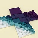
A simple ‘landscape’ of cubes follows the same pattern as our earlier reference marks. Two-dimensional Perlin noise governs their elevation.
Because perlinCubes is static, we need to pass a PApplet object into the function. Our sketch itself is a child of PApplet, so we pass this when we call perlinCubes in draw. The jagged scalar will be multiplied with noise offsets. We then update the main sketch.
noiseDetail can be called in setup to control the quality of noise generated as well. Four octaves with a falloff of 0.5 is the default. We could also use noiseSeed if we needed to cache the landscape’s appearance. For extra measure, we throw in a house model, loaded from an .obj file into a PShape.
A First-Person Shooter (FPS) Camera

Another complex case is that of the FPS camera, popularized by games like Doom, Call of Duty and so on. Here, avatar movement via key inputs must be combined with a perspective projection controlled with mouse inputs. We start with the class constructor and some important variables.
Among these variables are those to track key inputs associated with the pitch and yaw of the avatar’s head, and to simulate bobbing motion as the avatar walks. The constructor establishes a perspective projection looking forward. Next, we write a move function:
Movement is similar to the tank controls from earlier. We add a safeguard: the FPS will only update when the sketch has focus. When this function is called, the first parameter it will receive is the sketch’s focused variable. The left and right keys now strafe rather than rotation, so they reference the i variable inherited from Entity that stores its right axis of orientation. Last, if any keys have been pressed, movement direction and location are updated. A cosine wave driven by stepCount and dampened by headBobDamping drives the illusion of head bobbing.
Like the look functions earlier, a primary responsibility of this function is to update the axes of orientation, i, j and k. The difference is that rotateX and rotateY now dictate the rotation of the model-view matrix. These three vectors represent the avatar-camera’s orientation in the world — the camera-inverse — not the camera matrix. They are used to orient the move function.
In the main sketch, after an FPS object has been created, we can then call cam.move(focused, pressed); and cam.look(focused, mouseX, mouseY, width, height); in draw. A drawback to calling look in draw when a sketch is not fullScreen is that the mouse will default to (0, 0), meaning the avatar will start out looking at the sky. If this is problematic, we could separate the look function into smaller functions, one of which is called in the mouseMoved event listener. Another approach is to ensure there’s a title screen which the user has to click on to begin play.
Rethinking the GUI

In 2.5D, we placed our HP bar and background in the same renderer as the one updated by the camera. We reset matrices, avoiding the adverse effects of doing so by placing the background at the start of draw and the GUI at the end. In 3D, there are too many matrices for this to be an attractive technique. Instead, we use multiple renderers: a secondary renderer handles the camera and world while GUI and background will be treated as effects added in ‘post’.
While we revise our general strategy, we update our GUI’s aesthetic.
As a precaution, the GUI turns off any lights, disables depth-testing (so that it won’t be occluded by any objects in front of it) and ensures that the default shader is in use.
Our main sketch now looks like so:
All the drawing for the main renderer now must take place between beginDraw and endDraw. Renderers created with createGraphics may have translucent backgrounds.
Backgrounds
Last of all, we update the background.

We refer to the chapter on noise in The Book of Shaders, which in turn references Morgan McGuire’s GLSL implementation. The full code for our shader can be found here. There are many studies of the math behind Perlin noise, simplex noise and Voronoi-based noise out there — including the hash or random functions on which they depend — that will reward further study. The most immediate comparison to be made is with the Processing implementation.
Conclusion
With some basics laid down, we can begin to think about camera movement as a matter of design. We may ask how our avatar’s capabilities — what actions it performs in a virtual space — will impact the camera. For example, in a platforming game with predominantly horizontal motion, the camera may wait for the player to land on a platform before it smooths to a new position. By contrast, in a game where the avatar is falling down or climbing up deep mine shafts, the camera can not afford to wait. Technical talks at the Game Developer’s Conference (GDC) are a great way to explore these questions further.
Also, it’s worth reconceiving the single screen not as a limitation, but as a constraint. In artistic practice, constraints may be self-imposed or externally imposed, and can spur, rather than limit, the imagination. Ludum Dare 31, for example, challenged game developers to create a game which fits on one screen. Of particular note is Daniel Linssen’s birdsong.
Lastly, there comes a time when a camera must cease looking, the curtains must be drawn, and the elements on the stage rearranged. The techniques here hopefully prepare us to handle both sustained, smooth camera work as well as scene transitions.